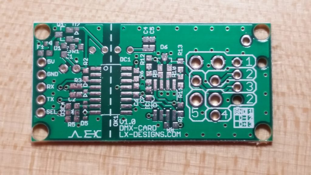
The DMX-Card is an isolated UART to RS-485 breakout board that supports the DMX-512 (ANSI E1.11) and RDM (ANSI E1.20) protocols. It was designed to allow hobbyists and tinkerers to quickly and easily add a DMX circuit to their projects while offering more advanced features such as electrical and optical data isolation as well as reverse-polarity, over-current and ESD protection. The card also features multiple footprints for output connectors, allowing users to select one of several options for the DMX output including 3-pin and 5-pin XLR sockets and standard 0.100″ headers.
Schematics, layouts, and Gerber files for the DMX-Card are available for download on Github. The project is made available through the Creative Commons Share-Alike license.
Features
- +5V input with polarity and over-current protection
- Full power and data isolation
- Isolated DC-DC converter (1.5kVDC)
- Isolated I/O via optocoupler (2.5kVDC)
- ESD/TVS protection on all data inputs and outputs (including DMX)
- Full DMX compliance*
- ANSI E1.20-2006 RDM compliant circuit, including correct biasing resistors (562/133/562)
- 10MBd optocouplers
- User-selectable I/O connectors:
- Output:
- Neutrik NC3FAH (3-pin XLR)
- Neutrik NC5FAH (5-pin XLR)
- 0.100″ PTH connectors (headers, screw terminal blocks, etc.)
- Input:
- 0.100″ PTH connectors (headers, screw terminal blocks, etc.)
- Output:
Physical
- Board Dimensions: 0.95″ x 1.90″ (24.13mm x 48.26mm) (Actual dimensions will vary depending on the type of output connector installed)
- Board Thickness: 1.6mm
- Input Power: +5VDC, 60mA (nominal)
- Input Connections: +5V, GND, RX, TX, RX/TX Select
- Output: Isolated RS-485/DMX-512 (Isolated GND, D-, D+)
- Mounting: 4x 0.125″ holes, located at edges of board
*circuit is constructed to ANSI E1.20; RDM must be correctly implemented on controller for full compliance